本文最后更新于 2025年2月10日 下午
屏幕后处理
MonoBehavior有这样一个函数:OnRenderImage(RenderTexture src, RenderTexture dest),在每帧渲染完成后调用。其中,第一个参数为当前完成渲染的图像,第二个参数为最终输出到屏幕上的图像。该函数默认在完成所有步透明、半透明物体的渲染后调用。如果想更改该函数的生效次序,使其在不透明物体渲染完毕后,半透明物体渲染前执行,则为其添加[ImageEffectOpaque]属性。
Graphics.Blit(Texture src, RenderTexture dest, Material mat, int pass = -1)用于将src纹理作为名为“_MainTex”的材质属性传递给mat对应的Shader。经过mat处理后,图像被输出到dest上。pass变量用于指定处理图像的Shader Pass序号,若为-1则从上到下执行所有Pass。
通常,我们完成后处理材质mat的编写后,直接在OnRenderImage中调用Graphics.Blit(src, dest, mat)即可。但有些情况下,我们需要分步对图像进行处理。此时,我们需要调用RenderTexture.GetTemporary(int RTWidth, int RTHeight, 0)来获取一张临时的RenderTexture作为Buffer,然后调用多次Blit函数。完成Blit后,记得调用RenderTexture.ReleaseTemporary(RenderTexture)释放内存。
屏幕后处理脚本需要绑定在相机上。
屏幕后处理对设备条件有所限制。为了检查设备是否满足条件,使用下列代码:
1
2
3
4
| protected bool CheckSupport(){
if(SystemInfo.supportsImageEffects == false || SystemInfo.supportsRenderTextures == false) return false;
else return true;
}
|
我们既可以直接从Shader创建后处理Mat并拖拽到脚本的Inspector,也可以根据Shader动态创建后处理Mat实例。代码如下:
1
2
3
4
5
6
7
8
9
10
11
| protected Material CheckShaderAndCreateMaterial(Shader shader, Material material){
if(shader == null) return null;
if(!shader.isSupported) return null;
if(material && material.shader == shader){
return material;
}
material = new Material(shader);
material.hideFlags = HideFlags.DontSave;
if(material) return material;
else return null;
}
|
基本调色
在MB脚本中定义变量brightness、saturation、contrast,可用Range属性修饰以控制范围。
在OnRenderImage中,使用material.SetFloat函数设置属性,并调用Graphics.Blit进行后处理。
在Shader中,定义同名的三个属性。对于后处理材质,起手式如下:
ZTest Always Cull Off ZWrite Off
Fallback Off
因为屏幕后处理本质上是绘制覆盖屏幕的面片,它需要始终通过深度测试,且不进行深度写入。
- 亮度是对最终颜色强度的直接处理,直接
color * _brightness即可。
- 饱和度是灰色与纯色之间的lerp因子。
- 对比度是图像亮部与暗部的比值。
FS如下:
1
2
3
4
5
6
7
8
9
10
11
12
| fixed4 frag(v2f i) : SV_Target{
fixed4 renderTex = tex2D(_MainTex, i.uv);
fixed3 finalColor = renderTex.rgb * _Brightness;
fixed luminance = dot(renderTex.rgb, fixed3(0.2125, 0.7154, 0.0721));
fixed3 luminanceColor = fixed3(luminance, luminance, luminance);
finalColor = lerp(luminanceColor, finalColor, _Saturation);
finalColor = (finalColor - 0.5) * _Contrast + 0.5;
return fixed4(finalColor, renderTex.a);
}
|
边缘检测
通过卷积完成。
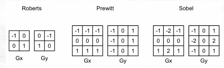
常见的边缘检测算子如下:
OnRenderImage函数同样是先设置材质属性,然后通过Graphics.Blit进行后处理。
v2f中,需要将原本的half2 uv改为half2 uv[9]
VS中,使用_MainTex_TexelSize.xy获取纹素尺寸,并按顺序获取主像素周围的8个像素的纹理坐标:
1
2
3
4
5
6
7
8
| v2f vert(appdata_img v){
v2f o;
o.pos = mul(UNITY_MATRIX_MVP, v.vertex);
half2 uv = v.texcoord;
o.uv[0] = uv + _MainTex_TexelSize.xy * half2(-1,-1);
return o;
}
|
FS中,将颜色灰度化,并将灰度化后的颜色使用Sobel算子进行卷积:
1
2
3
4
5
6
7
8
9
10
11
12
13
14
15
16
17
18
19
20
21
22
23
| fixed luminance(fixed4 color){
return 0.2125 * color.r + 0.7154 * color.g + 0.0721 * color.b;
}
half Sobel(v2f i){
const half Gx[9] = {-1,-2,-1,0,0,0,1,2,1};
const half Gy[9] = {-1,0,1,-2,0,2,-1,0,1};
half texColor;
half edgeX = 0;
half edgeY = 0;
for(int it=0;it<9;it++){
texColor = luminance(tex2D(_MainTex,i.uv[it]));
edgeX += texColor * Gx[it];
edgeY += texColor * Gy[it];
}
half edge = 1- abs(edgeX) - abs(edgeY);
return edge;
}
fixed4 fragSobel(v2f i) : SV_Target{
half edge = Sobel(i);
fixed4 withEdgeColor = lerp(_EdgeColor, tex2D(_MainTex, i.uv[4], edge));
fixed4 onlyEdgeColor = lerp(_EdgeColor, _BackgroundColor, edge);
return lerp(withEdgeColor, onlyEdgeColor, _EdgeOnly);
}
|
记得Fallback Off。
高斯模糊
二维高斯卷积核会导致迭代次数过多。我们可以将其拆分为两个一维卷积核,分别卷积水平和垂直方向。首先,在第一个Pass里进行水平方向卷积,将结果存储在Buffer中,然后在第二个Pass里使用上一步的结果进行垂直方向卷积。
高斯模糊不需要原图分辨率那么高的精度,所以可以对图像进行缩放后再模糊,可以大大减少运算量:
1
2
3
4
5
6
7
8
9
10
11
12
13
14
15
16
17
18
19
20
21
22
23
24
| void OnRenderImage(RenderTexture src, RenderTexture dest){
if(material){
int rtW = src.width/downSample;
int rtH = src.height/downSample;
RenderTexture buffer0 = RenderTexture.GetTemporary(rtW, rtH, 0);
buffer0.filterMode = FilterMode.Bilinear;
Graphics.Blit(src, buffer0, 0);
for(int i=0;i<iterations;i++){
material.setFloat("_BlurSize",1.0f+i*blurSpeed);
RenderTexture buffer1 = RenderTexture.GetTemporary(rtW, rtH, 0);
Graphics.Blit(buffer0, buffer1, material, 0);
RenderTexture.ReleaseTemporary(buffer0);
buffer0 = buffer1;
buffer1 = RenderTexture.GetTemporary(rtW, rtH, 0);
Graphics.Blit(buffer0, buffer1, material, 1);
buffer0 = buffer1;
}
Graphics.Blit(buffer0, dest);
RenderTexture.ReleaseTemporary(buffer0);
}
else{
Graphics.Blit(src, dest);
}
}
|
关键FS代码:
1
2
3
4
5
6
7
8
9
10
| fixed4 fragBlur(v2f i) : SV_Target{
float weight[3] = {0.4026, 0.2442, 0.0545};
fixed3 sum = tex2D(_MainTex, i.uv[0]).rgb * weight[0];
for(int it = 1; it<3; it++){
sum += tex2D(_MainTex, i.uv[it*2-1]).rgb * weight[it];
sum += tex2D(_MainTex, i.uv[2*it]).rgb * weight[it];
}
return fixed4(sum, 1.0);
}
|
泛光
泛光的步骤如下:
- 首先,根据一个阈值提取出图像的较亮区域,将其存储在一张RT中
- 然后,对此RT进行高斯模糊
- 最后,将模糊的结果与原图像混合
OnRenderImage如下:
1
2
3
4
5
6
7
8
9
10
11
12
13
14
15
16
17
18
19
20
21
22
23
24
25
26
27
28
29
| void OnRenderImage(RenderTexture src, RenderTexture dest){
if(material != null){\
material.setFloat("_LuminanceThreshold", luminanceThreshold);
int rtW = src.width / downSample;
int rtH = src.height / downSample;
RenderTexture buffer0 = RenderTexture.GetTemporary(rtW, rtH, 0);
buffer0.filterMode = FilterMode.Bilinear;
Graphics.Blit(src, buffer0, material, 0);
for(int i=0; i<iterations; i++){
material.setFloat("_BlurSize", 1.0f + i*blurSpread);
RenderTexture buffer1 = RenderTexture.GetTemporary(rtW, rtH, 0);
Graphics.Blit(buffer0, buffer1, material, 1);
RenderTexture.ReleaseTemporary(buffer0);
buffer0 = buffer1;
buffer1 = RenderTexture.GetTemporary(rtW, rtH, 0);
Graphics.Blit(buffer0, buffer1, material, 2);
RenderTexture.ReleaseTemporary(buffer0);
buffer0 = buffer1;
}
material.setTexture("_Bloom", buffer0);
Graphics.Blit(src, dest, material,3);
RenderTexture.ReleaseTemporary(buffer0);
} else Graphics.Blit(src,dest);
}
|
Shader代码略。
运动模糊
常见的运动模糊实现策略有累计缓存(Accumulation Buffer)和速度缓存(Velocity Buffer)。前者取多帧连续图像的平均值作为输出,但性能消耗非常大;后者存储各像素当前的运动速度,依次决定模糊的方向和大小。这里我们使用方法一。
OnRenderImage如下:
1
2
3
4
5
6
7
8
9
10
11
12
13
14
| void OnRenderImage(RenderTexture src, RenderTexture dest){
if(material != null){
if(accumulationTexture == null || accumulationTexture.width != src.width || accumulationTexture.height != src.height){
DestroyImmediate(accumulationTexture);
accumulationTexture = new RenderTexture(sec.width, src.height, 0);
accumulationTexture.hideFlags = HideFlags.HideAndDontSave;
Graphics.Blit(src, accumulationTexture);
}
accumulationTexture.MarkRestoreExpected();
material.SetFloat("_BlurAmount", 1.0f - blurAmount);
Graphics.Blit(src, accumulationTexture, material);
Graphics.Blit(accumulationTexture, dest);
}else Graphics.Blit(src, dest);
}
|
Shader的两个Pass非常简单,第一个Pass设置ColorMask RGB,第二个Pass设置ColorMask A。之所以将RGB和A通道分开是为了A通道由_BlurAmount控制,表示模糊的强度。
使用深度、法线纹理
对于某些高级的屏幕后处理效果,仅获取屏幕颜色信息是不够的,还需要像G-Buffer一样,获取屏幕空间的深度和法线信息。
对于深度纹理:
使用延迟渲染管线时,深度纹理存储在G-Buffer中,自然可以直接访问。使用前向渲染管线时,需要用一个单独的Pass渲染得到。在Unity中,只有RenderType为“Background”、“Geometry”和“AlphaTest”的物体可以被渲染到深度、法线纹理。
如果只需要深度纹理,那Unity会直接使用ShadowCaster Pass(一般存在于Fallback中)来得到深度纹理。
如果需要深度+法线纹理,Unity会创建一张分辨率与屏幕相同,格式为ARGB32的纹理。其中,观察空间下的法线被编码进R、G通道,深度信息编码入B和A通道。
通过设置Camera组件的depthTextureMode属性为DepthTextureMode.Depth,Unity就会声明全局Shader属性_CameraDepthTexture,内部存储有深度纹理。设置为DepthTextureMode.DepthNormals,则会声明_CameraDepthNormalsTexture,存储有深度+法线纹理。DepthTextureMode是Flag,可以通过或(“|”)的形式同时声明多种模式。
采样深度纹理时,我们通过SAMPLE_DEPTH_TEXTURE宏进行,以避免平台不同导致的差错。也可以通过SAMPLE_DEPTH_TEXTURE_PROJ(_CameraDepthTexture, UNITY_PROJ_COORD(i.scrPos))采样,其中scrPos为使用ComputeScreenPos函数计算得到的屏幕空间坐标。
通过上述方式采样得到的深度值是非线性变化的,但我们实际需要的是线性变化的深度值。为此,我们需要使用LinearEyeDepth或Linear01Depth对采样值进行转换。前者返回取值范围在[Near, Far]的深度值,后者返回[0,1]范围内的深度值。
若需要采样_CameraDepthNormalsTexture采样深度及法线,则使用下面的函数:
void DecodeDepthNormal(float4 enc, out float depth, out float3 normal),其内部调用了DecodeFloatRG和DecodeViewNormalStereo方法。
优化运动模糊
前面提到,更优的运动模糊实现方式是使用速度映射图,即存储每个像素的速度。我们可以通过深度图重建每个像素的世界坐标,然后将当前帧的像素世界坐标通过前一帧的VP矩阵进行变换,得到此位置在前一帧的NDC坐标。随后,计算前一帧和当前帧的位置差,即可生成该像素的速度。步骤如下:
- 首先,在MB脚本中定义
Matrix4x4变量previousViewProjectionMatrix,用于保存上一帧的VP矩阵。
- 在MB脚本中设置
camera.depthTextureMode |= DepthTextureMode.Depth,以开启深度图渲染
OnRenderImage如下:
1
2
3
4
5
6
7
8
9
10
11
| void OnRenderImage(RenderTexture src, RenderTexture dest){
if(material!=null){
material.SetFloat("_BlurSize", blurSize);
material.SetMatrix("_PreviousViewProjectionMatrix", previousViewProjectionMatrix);
Matrix4x4 currentrViewProjectionMatrix = camera.projectionMatrix * camera.worldToCameraMatrix;
Matrix4x4 currentViewProjectionInverseMatrix = currentViewProjectionMatrix.inverse;
material.SetMatrix("_CurrentViewProjectionInverseMatrix, currentViewProjectionInverseMatrix");
previousViewProjectionMatrix = currentViewProjectionMatrix;
Graphics.Blit(src, dest, material);
} else Graphics.Blit(src,dest);
}
|
其中,当前VP矩阵的逆矩阵用于将当前片段还原到世界坐标;上一帧的VP矩阵用于将当前片段的世界坐标变换到上一帧的NDC坐标。
- Shader如下:
VS:
1
2
3
4
5
6
7
8
9
10
11
12
13
14
15
| struct v2f{
float4 pos : SV_POSITION;
half2 uv : TEXCOORD0;
half2 uv_depth : TEXCOORD1;
}
v2f vert(appdata_img v){
v2f o;
o.pos = mul(UNITY_MATRIX_MVP, v.vertex);
o.uv = v.texcoord;
o.uv_depth = v.texcoord;
#if UNITY_UV_STARTS_AT_TOP
o.uv_depth.y = 1-o.uv_depths.y;
#endif
return o;
}
|
FS:
1
2
3
4
5
6
7
8
9
10
11
12
13
14
15
16
17
18
19
| fixed4 frag(v2f i) : SV_Target{
float d = SAMPLE_DEPTH_TEXTURE(_CameraDepthTexture, i.uv_depth);
float4 H = float4(i.uv.x*2-1, i.uv.y*2-1, d*2-1, 1);
float4 D = mul(_CurrentViewProjectionInverseMatrix, H);
float4 worldPos = D/D.w;
float4 currentPos = H;
float4 previousPos = mul(_PreviousViewProjectionMatrix, worldPos);
previousPos /= previousPos.w;
float2 velocity = (currentPos.xy - previousPos.xy)/2.0f;
float2 uv = i.uv;
float4 c = tex2D(_MainTex, uv);
uv += velocity * _BlurSize;
for(int it = 1; it<3; it++, uv+=velocity*_BlurSize){
float4 currentColor = tex2D(_MainTex, uv);
c+=currentColor;
}
c/=3;
return fixed4(c.rgb,1.0);
}
|
记得关闭Fallback。
全局雾效
原理
在Unity中,可以通过#pragma multi_compile_fog指令、UNITY_FOG-COORDS、UNITY_TRANSFER_FOG、UNITY_APPLY_FOG等内置宏开启雾效。然而,使用这种方法无法对雾效进行精确的控制。
屏幕后处理雾效是一种灵活的全局雾效方案,其关键点在于通过深度纹理重计算出各像素的世界坐标。在上一节运动模糊中,我们使用下列代码重计算世界坐标:
1
2
3
4
| float d = SAMPLE_DEPTH_TEXTURE(_CameraDepthTexture, i.uv_depth);
float4 H = float4(i.uv.x*2-1, i.uv.y*2-1, d*2-1, 1);
float4 D = mul(_CurrentViewProjectionInverseMatrix, H);
float4 worldPos = D/D.w;
|
然而,对此方法来说,矩阵变换是不可避免的,而这对性能要求较高。在本节,我们将学习基于射线插值的重建世界坐标方法。
在世界坐标系中,一个顶点的位置可以通过另一个顶点坐标+一个偏移量得到。因此,我们只需要知道摄像机的位置,并得到像素相对于相机在世界空间下的偏移量,就能得到像素的世界坐标。代码如下:
float4 worldPos = _WorldSpaceCameraPos + linearDepth * interpolatedRay;
其中,_WorldSpaceCameraPos为世界空间相机位置,linearDepth为深度纹理采样、转换得到的线性深度值,interpolatedRay为VS输出并插值得到的射线,它包含了像素到摄像机的方向和距离信息。
下面详细阐述原理。
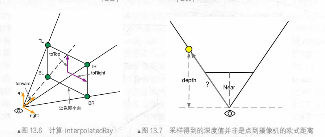
如图,图13.6中的矩形是摄像机近平面,TL、TR、BL和BR是近平面的四个角。通过下列公式,我们可以得到TL、TR、BL、BR点在相机坐标系下的位置:
TL=camera.forward⋅Near+toTop−toRight
TR=camera.forward⋅Near+toTop+toRight
BL=camera.forward⋅Near−toTop−toRight
BR=camera.forward⋅Near−toTop+toRight
其中,toTop、toRight为:起点位于近平面中心,指向摄像机正上方和正右方,模长为近平面高度一半的向量。公式如下:
halfHeight=Near∗tan(2FOV)
此处,FOV为垂直FOV。halfHeight为近平面高度的一半。
toTop=camera.up∗halfHeight
toRight=camera.right∗halfHeight.aspect
完成向量计算后,根据图13.7中相似三角形,可以计算出任意点距离摄像机的距离dist:
dist=Near∣射线向量∣×depth
其中,射线向量模长由VS插值获得。
计算
首先,我们需要一个雾效系数f作为混合原始颜色和雾的颜色的Lerp因子。雾效系数有线性、指数和指数平方三种计算方式。分别如下:
本节中,我们使用线性雾,但并非基于距离,而是基于高度:$$f=\frac{h_{max}-|z|}{h_{max}-h_{min}}$$
MB脚本如下:
1
2
3
4
5
6
7
8
9
10
11
12
13
14
15
16
17
18
19
20
21
22
23
24
25
26
27
28
29
30
31
32
33
34
35
36
37
38
39
40
41
42
43
| void OnEnable(){
camera.depthTextureMode |= DepthTextureMode.Depth;
}
void OnRenderImage(RenderTexture src, RenderTexture dest){
if(material){
Matrix4x4 frustumCorners = Matrix4x4 identity;
float fov = camera.fieldOfView;
float near = camera.nearClipPlane;
float far = camera.farClipPlane;
float aspect = camera.aspect;
float halfHeight = near * Mathf.Tan(fov*0.5f*Mathf.Deg2Rad);
Vector3 toRight = cameraTransform.right * halfHeight * aspect;
Vector3 toTop = cameraTransform.up * halfHeight;
Vector3 topLeft = cameraTransform.forward * near + toTop - toRight;
float scale = topLeft.magnitude / near;
topLeft.Normalize();
topLeft *= scale;
Vector3 topRight = cameraTransform.forward * near + top + toRight;
topRight.Normalize();
topRight *= scale;
Vector3 bottomLeft = cameraTransform.forward * near - top - toRight;
BottomLeft.Normalize();
bottomLeft *= scale;
Vector3 bottomRight = cameraTransform.forward * near - top + toRight;
bottomRight.Normalize();
bottomRight *= scale;
frustumCorners.SetRow(0, bottomLeft);
frustumCorners.SetRow(1, bottomRight);
frustumCorners.SetRow(2, topRight);
frustumCorners.SetRow(3, topLeft) ;
material.SetMatrix("_FrustumCornersRay", frustumCorners);
material.SetMatrix("_ViewProjectionInverseMatrix", (camera.projectionMatrix * camera.worldToCameraMatirx).inverse);
material.SetFloat("_FogDensity", fogDensity);
}
}
|
VS如下:
1
2
3
4
5
6
7
8
9
10
11
12
13
14
15
16
17
18
19
20
21
22
23
24
25
26
27
28
| struct v2f{
float4 pos : SV_POSITION;
half2 uv : TEXCOORD0;
half2 uv_depth : TEXCOORD1;
float4 interpolatedRay : TEXCOORD2;
};
v2f vert(appdata_img v){
v2f o;
o.pos = mul(UNITY_MATRIX_MVP, v.vertex);
o.uv = v.texcoord;
o.uv_depth = v.texcoord;
#if UNITY_UV_STARTS_AT_TOP
if(_MainTex_TexelSize.y < 0){
o.uv.depth.y =
}
#endif
int index = 0;
if(v.texcoord.x < 0.5 && v.texcoord.y < 0.5) index = 0;
else if(v.texcoord.x > 0.5 && v.texcoord.y < 0.5) index = 1;
else if(v.texcoord.x < 0.5 && v.texcoord.y > 0.5) index = 2;
else index=3;
#if UNITY_UV_STARTS_AT_TOP
if(_MainTex_TexelSize.y < 0) index = 3-index;
#endif
o.interpolatedRay = _FrustumCornersRay[index];
return o;
}
|
FS:
1
2
3
4
5
6
7
8
9
| fixed4 frag(v2f i) : SV_Target{
float linearDepth = LinearEyeDepth(SAMPLE_DEPTH_TEXTURE(_CameraDepthTexture, i.uv_depth));
float3 worldPos = _WorldSpaceCameraPos + linearDepth * i.interpolatedRay.xyz;
float fogDensity = (_FogEnd - worldPos.y) / (_FogEnd - _FogStart);
fogDensity = saturate(fogDensity * _FogDensity);
fixed4 finalColor = tex2D(_MainTex, i.uv);
finalColor.rgb = lerp(finalColor.rgb, _FogColor.rgb, fogDensity);
return finalcolor;
}
|
记得关闭Fallback。
优化边缘检测
本质上是把原先的卷积Color变为卷积DepthNormal,没有很大的区别,所以略。
NPR
卡渲
轮廓线
有下列五种方案:
- 基于菲涅尔的N dot V描边。简单快速,效果一般。
- 双Pass渲染。简单快速,效果较好,但不适合平整模型。
- 边缘检测。适用于任意模型,但深度、法线变化较小的轮廓无法检测。
- 轮廓边检测。即检查某条边相邻的三角形是否满足$$(n_0 · v > 0)!=(n_1·v>0)$$。存在动画连贯性问题。
- 混合方案。
我们采用双Pass方案。在第一个Pass中,将模型顶点沿法线略微扩张,并且Cull Front。再渲染第二个Pass。核心代码如下:
1
2
3
4
|
viewNormal.z = -0.5;
viewNormal = normalize(viewNormal);
viewPos = viewPos + viewNormal * _Outline;
|
我该如何理解第一个Pass的Cull Front?
实际上,我们看到的描边线是模型外壳的内部。
镜面反射
前面提到,Blinn-Phong模型的镜面反射项如下:
float spec = pow(max(0.0,dot(normal, halfDir),_Gloss)
对于NPR的镜面反射,我们需要对spec进行step,以模拟小范围的纯色。
1
2
| float spec = dot(worldNormal, worldHalfDir);
spec = lerp(0,1,smoothstep(-w, w, spec - threshold));.
|
其中,w是一个很小的数值,可以理解为镜面反射区域与其他区域的过渡的宽度。之所以这么干是为了防止镜面反射的锯齿。
w的数值既可以设置为极小的定值,也可以设置为fwidth(spec)。
fwidth(x)用于计算当前像素与邻近像素的x变量的差值。也就是说,邻近像素的x值变化越大,函数返回值就越大。
代码
VS:
1
2
3
4
5
6
7
8
9
10
11
12
13
14
15
16
| struct v2f{
float4 pos : POSITION;
float2 uv : TEXCOORD0;
float3 worldNormal : TEXCOORD1;
float3 worldPos : TEXCOORD2;
SHADOW_COORDS(3)
}
v2f vert (a2f v){
v2f o;
o.pos = mul(UNITY_MATRIX_MVP, v.vertex);
o.uv = TRANSFORM_TEX(v.texcoord, _MainTex);
o.worldNormal = mul(v.normal, (float3x3)_World2Object);
o.worldPos = mul(_Object2World, v.vertex).xyz;
TRANSFER_SHADOW(o);
return o;
}
|
FS:
1
2
3
4
5
6
7
8
9
10
11
12
13
14
15
16
17
| float4 frag(v2f i) : SV_Target{
fixed3 worldNormal = normalize(i.worldNormal);
fixed3 worldLightDir = normalize(UnityWorldSpaceLightDir(i.worldPos));
fixed3 worldViewDir = normalize(UnityWorldSpaceViewDir(i.worldPos));
fixed3 worldHalfDir = normalize(worldLightDir + worldViewDir);
fixed4 c = tex2D(_MainTex, i.uv);
fixed3 albedo = c.rgb * _Color.rgb;
fixed3 ambient = UNITY_LIGHTMODEL_AMBIENT.xyz * albedo;
UNITY_LIGHT_ATTENUATION(atten, i, i.worldPos);
fixed diff = dot(worldNormal, worldLightDir);
diff = (diff * 0.5 + 0.5) * atten;
fixed3 diffuse = _LightColor0.rgb * albedo * tex2D(_Ramp, float2(diff, diff)).rgb;
fixed spec = dot(worldNormal, worldHalfDir);
fixed w = fwidth(spec) * 2.0;
fixed3 specular = _Specular.rgb * lerp(0, 1, smoothstep(-w, w, spec + _SpecularScale - 1)) * step(0.0001, _SpecularScale);
return fixed4(ambient + diffuse + specular, 1.0);
}
|
记得Fallback “Diffuse”
基于TAM的风格化渲染
色调艺术映射(Tonal Art Map, TAM)是一系列纹理,对应不同光照强度下所采用的类似于光照贴图的结构。如下:
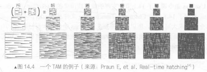
在本节,我们不考虑TAM中的Mipmap,而是单纯用六张纹理进行渲染。在VS渲染阶段,我们计算逐顶点光照,并根据结果决定六张纹理的混合权重,并传递给FS。
VS:
1
2
3
4
5
6
7
8
9
10
11
12
13
14
15
16
17
18
19
20
21
22
23
24
25
26
27
28
29
30
31
32
33
34
35
36
37
38
39
40
41
42
43
44
| struct v2f{
float4 pos : SV_POSITION;
float2 uv : TEXCOORD0;
fixed3 hatchWeights0 : TEXCOORD1;
fixed3 hatchWeights1 : TEXCOORD2;
float3 worldPos : TEXCOORD3;
SHADOW_COORDS(4)
};
v2f vert(a2v v){
v2f o;
o.pos = mul(UNITY_MATRIX_MVP, v.vertex);
o.uv = v.texcoord.xy * _TileFactor;
fixed3 worldLightDir = normalize(WorldSpaceLightDir(v.vertex));
fixed3 worldNormal = UnityObjectToWorldNormal(v.normal);
fixed diff = max(0, dot(worldLightDir, worldNormal));
o.hatchWeights0 = fixed3(0,0,0);
o.hatchWeights1 = fixed3(0,0,0);
float hatchFacotr = diff * 7.0;
if (hatchFactor > 6. 0){
} else if (hatch Factor > 5. 0) {
o.hatchWeights0.x = hatchFactor - 5.0;
} else if (hatchFactor > 4.0) {
o.hatchWeights0.x = hatchFactor - 4.0;
o.hatchWeights0.y = 1.0 - o.hatchWeights0.x;
} else if (hatchFactor > 3. 0) {
o.hatchWeights0.y = hatchFactor - 3.0;
o.hatchWeights0.z = 1.0 - o.hatchWeights0.y;
} else if (hatchFactor > 2. 0) {
o.hatchWeights0.z = hatchFactor - 2.0;
o.hatchWeights1.x = 1 . 0 - o.hatchWeights0.z;
} else if (hatchFactor > 1. 0) {
o.hatchWeights1.x = hatchFactor - 1.0;
o.hatchWeights1.y = 1.0 - o.hatchWeights1.x;
} else {
o.hatchWeights1.y = hatchFactor;
o.hatchWeights1.z = 1.0 - o .hatchWeights1.y;
}
o.worldPos = mul(_Object2World, v.vertex).xyz;
TRANSFER_SHADOW(o);
return o;
}
|
FS:
1
2
3
4
5
6
7
8
9
10
11
12
| fixed4 frag(v2f i) : SV_Target{
fixed4 hatchTex0 = tex2D(_Hatch0, i.uv) * i.hatchWeights0.x;
fixed4 hatchTex1 = tex2D(_Hatch1, i.uv) * i.hatchWeights0.y;
fixed4 hatchTex2 = tex2D(_Hatch2, i.uv) * i.hatchWeights0.z;
fixed4 hatchTex3 = tex2D(_Hatch3, i.uv) * i.hatchWeights1.x;
fixed4 hatchTex4 = tex2D(_Hatch4, i.uv) * i.hatchWeights1.y;
fixed4 hatchTex5 = tex2D(_Hatch5, i.uv) * i.hatchWeights1.z;
fixed4 whiteColor = fixed4(1,1,1,1) * (1-i.hatchWeight0.x - i.hatchWeights0.y - i.hatchWeights0.z - i.hatchWeights1.x - i.hatchWeights1.y - i.hatchWeights1.z);
fixed4 hatchColor = hatchTex0 + hatchTex1 + hatchTex2 + hatchTex3 + hatchTex4 + hatchTex5 + whiteColor;
UNITY_LIGHT_ATTENUATION(atten, i, i.worldPos);
return fixed4(hatchColor.rgb * _Color.rgb * atten, 1.0);
}
|
记得设置Fallback “Diffuse”。